

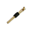
As soon as a resistance in the milliohm range has to be measured, the test contact itself becomes the largest error in the measuring chain. Our Kelvin probes solve this problem where it arises: they grip the terminal pin of the device under test with two electrically separated contact blades and thus establish the current path and the sense path in a single mating movement.
What sets a Kelvin probe apart from a test probe
A classic spring contact probe consists of a barrel, a plunger and a spring, and contacts a single point. A four-wire measurement would require two of them – and on the same pin there is usually no room for that. A Kelvin probe therefore works differently: two opposing, pre-tensioned and gold-plated contact blades are electrically separated by an insulating body. The pre-tension provides the defined contact pressure, the separation provides two independent paths at one and the same contact point.
This results in the properties that have made this design so widespread in test engineering:
- Low insertion forces – the device under test is gripped, not pierced – damage to the terminal pin is ruled out
- Low contact resistance – between 0.8 and 20 mOhm depending on type, and therefore reproducible enough for measurements in the milliohm range
- High current rating – from 3 A for the smallest designs up to 40 A for the blade terminal probes
- Fatigue-resistant design – the contact blades work within the pre-tensioned range and not at the elastic limit
- High mating cycle endurance – 100,000 to 300,000 cycles depending on type without appreciable wear
- Fast assembly – the designs are intended for installation in test adapters and contacting fixtures
Where four-wire measurement is needed
Whenever the resistance to be measured is of the same order of magnitude as the leads and contacts of the test fixture. Typical test tasks are crimped and welded joints, cell connectors and busbars in battery modules, motor and transformer windings, shunts and fuses, relay and connector contacts, and continuity measurements in wiring harnesses.
How the method works in detail, why the voltage tap has to be on the inside and from which order of magnitude the effort pays off is explained on our page about four-wire measurement.
Our range
Nine designs cover the common centre distances from 2.40 to 7.00 mm as well as round and blade terminals:
UE53-P-100 / UE53-P-150
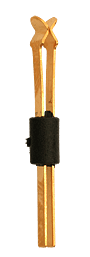
Centres: 2,54 / 3,75mm
design: 1,80 / 2,93 mm
Nominal length: 26,30 / 26,00 mm
Rated current: 6 / 8 A
Contact resistance: 20 / 20 mΩ
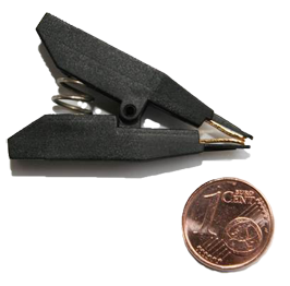
UE53-P-085
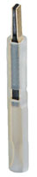
Centres: 2,40 mm
design: 2.00 mm, double-ended
Nominal length: 20.10 mm
Rated current: 10 A
Contact resistance: 5 mΩ
UE53-P-090
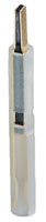
Centres: 2,40 mm
design: 2.00 mm
Nominal length: 20.10 mm
Rated current: 10 A
Contact resistance: 5 mΩ
UE53-P-095
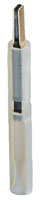
Centres: 2,40 mm
design: 2.00 mm
Nominal length: 20.10 mm
Rated current: 10 A
Contact resistance: 5 mΩ
UE53-P-125
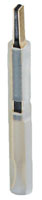
Centres: 2,54 mm
design: 3.00 mm
Nominal length: 27.00 mm
Rated current: 10 A
Contact resistance: 4 mΩ
UE53-P-165

Centres: 4,20 mm
design: for blade terminals
Nominal length: 31.50 mm
Rated current: 20 A
Contact resistance: 1.7 mΩ
UE53-P-275

Centres: 7,00 mm
design: for blade terminals
Nominal length: 31.60 mm
Rated current: 40 A
Contact resistance: 0.8 mΩ
Subject to changes and errors.
Which probe for which device under test?
- Round and blade terminals on tight centres – UE53-P-085, -090 and -095 work from 2.40 mm centre distance; the -085 version is double-ended
- Standard 2.54 mm centres – UE53-P-100 for small currents, UE53-P-125 for 10 A at only 4 mOhm contact resistance
- 3.75 mm centres – UE53-P-150 as a robust version with 2.93 mm diameter
- Blade terminals and high current – UE53-P-165 for 20 A on 4.20 mm centres, UE53-P-275 for 40 A on 7.00 mm centres at 0.8 mOhm
If none of the standard designs suits your device under test, we design the contacting as a custom solution – that has been our daily business since 1994.
Four-wire measurement in semiconductor test
The same measuring principle appears in semiconductor test in a completely different design: there, two separately sprung contacts sit around 0.125 mm apart within a pitch of 0.5 mm, in order to measure four-wire on a single ball of a BGA. If that is your field, our test socket section takes you further.
Let's discuss your measuring task
Tell us the terminal shape, the centre distance, the test current and the required accuracy – we will propose the right design or engineer the contacting. Phone +49 89 4411900.