

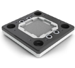
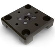
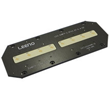
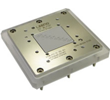
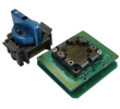
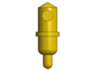
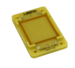
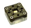
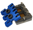
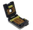
A test socket with pogo pins establishes an electrical connection to an integrated circuit without soldering it – repeatably, non-destructively, and several hundred thousand times over. As a specialist in contact technology, uwe electronic supplies pogo pin test sockets for BGA, QFN, QFP, WLCSP, PoP and many other package types: from a single socket for laboratory characterisation to a multisite socket for production test on the handler. Standard solutions, modified variants and complete custom designs based on your component drawing.
What is a test socket with pogo pins?
At its core, a test socket consists of a body made of high-performance plastic fitted with spring-loaded contact pins – the pogo pins. The socket is mounted on the load board of the test system and holds the device under test (DUT). Each terminal of the device is contacted by its own spring probe, which passes the signal on to the load board and thus to the tester.
A pogo pin is a precision component made up of three elements: a barrel, a movable plunger and an internal spring. The travel of that spring is decisive for contact quality – it compensates for coplanarity tolerances of the solder balls, height differences and manufacturing tolerances of the package, and ensures that every single terminal is contacted with a defined, uniform force. Depending on the application, the contact tip is designed as a crown, a point or a flat head; a crown tip penetrates the oxide layer on the solder ball as it lands and thus creates a stable, low-resistance transition.
The dimensions show just how finely these contacts are built: fine-pitch probes for semiconductor test have barrel diameters of around 0.08 mm, while RF versions measure 0.25 mm with lengths from 0.85 mm.
Inside the socket, the contacts are usually not rigidly fixed but float in a stepped bore. This is elegant in design terms: a single spring-loaded head is enough to make a reliable connection in both directions – towards the load board and towards the device. When the socket is screwed onto the load board, the contacts are pushed up in their bores against the shoulder. As a result, they sit in the socket so that all of the remaining spring travel is available towards the device – exactly where it is needed during contacting.
A practical calculation shows the forces involved: at roughly 34 g of spring force per pin and 2,000 pins, some 68 kg act on an area of just 60 mm². This is precisely why the mechanical design of the socket, the choice of materials and the support of the load board are not side issues – they largely determine service life and measurement stability.
Why are pogo pin test sockets suited to mass production?
In production test, one figure matters above all: how many devices can be contacted before maintenance is due? With good cleaning, high-quality spring contacts typically withstand 200,000 to 300,000 test cycles. That amounts to a very long service life – and maintenance usually does not mean replacing the socket, but cleaning it and, where necessary, exchanging individual contacts.
- Long service life: 200,000 to 300,000 contact cycles per set of contacts with disciplined cleaning.
- Short cycle times: insert the device, close the lid, test, remove – no soldering and no warm-up time.
- Maintainable in operation: individual contacts can be replaced, and depending on the design, cleaning is possible directly at the test station.
- Scalable: multisite arrangements test several devices simultaneously and significantly reduce test time per device.
- Reproducible: the defined spring force per pin is maintained throughout the service life – measurements stay comparable.
How does a pogo pin test socket work?
The test sequence follows the same principle for almost all designs:
- The socket is mounted precisely on the load board and screwed down. In the process, the contacts are pushed up in their stepped bores against the shoulder, so that the spring travel is available towards the device. Dowel pins secure exact alignment with the contact pads of the board.
- he device is placed into the nest. The floating nest pre-centres it before the device meets the contacts – this prevents lateral forces and protects both the solder balls and the contact tips. The term “floating” is historical: the plate is not freely floating but spring-mounted.
- The lid is closed. With a clamshell lid, a screwing movement of the pusher follows: it presses the device down onto the contacts in a controlled manner and thus builds up the defined contact force. The spring probes are compressed by their working travel.
- The tester performs the measurement – from simple continuity and DC tests through functional tests to high-frequency measurements.
- The lid is opened, the device removed and the next one inserted.
Since small amounts of solder material, oxide and particles remain on the contact tips with every cycle, regular cleaning is an integral part of the process – as a guide value roughly every 50,000 cycles, depending on device, solder alloy and test environment. Cleaning is the single most important factor in actually reaching those 200,000 to 300,000 test cycles.
Where are pogo pin test sockets used?
Test sockets accompany a semiconductor throughout its entire life cycle – from the first samples to volume production:
- Development and characterisation: bring-up of new devices, parametric measurements and limit testing in the laboratory, usually with manually operated clamshell sockets.
- Validation and qualification: testing across temperature and voltage, frequently combined with a thermal streamer for hot and cold measurements.
- Failure analysis: reproducing and isolating failures on individual devices without having to solder them down.
- Production and final test: operation on ATE systems with a handler, often as a multisite solution for several devices at once.
- Burn-in and preconditioning: sustained stress at elevated temperature to screen out early failures.
- Programming before assembly: flashing memories and controllers before the devices are soldered onto the PCB.
- Wafer-level test: interposer sockets as an economical alternative to the probe card when testing WLCSP devices.
Typical user industries are semiconductor manufacturers and test service providers, automotive and aerospace suppliers, embedded and laser technology, as well as manufacturers of memory and camera modules.
Which packages can be tested with pogo pin test sockets?
In principle, any package whose terminals are accessible from the outside can be contacted. In practice, our range covers the entire common spectrum:
| Package family | Examples | Typical pitch range |
|---|---|---|
| Ball Grid Array | BGA, FBGA, CSP-BGA, PoP (Package-on-Package) | 0,3 – 1,0 mm |
| Land Grid Array | LGA, CSP-LGA | from 0,4 mm |
| Leadless / Leaded | QFN, QFP, SOP, TSSOP, TO, SOT | 0,35 – 0,8 mm |
| Wafer Level | WLCSP, Flip Chip (FC) | from 0,25 mm |
| Steckbare Gehäuse | PGA | from 1,0 mm |
| Module | Camera modules, memory modules, strip test | from 0,15 mm (Rohmaterialtest) |
Fine pitches, high pin counts and RF requirements are not mutually exclusive: our air-coaxial RF sockets achieve bandwidths of up to 40 GHz with 50 Ω impedance matching, and elastomer sockets at 0.35 mm pitch reach up to 34 GHz (at –1 dB).
Our test socket range at a glance
BGA, logic and SoC test sockets
For devices with high pin counts and fine pitch – from BGA and LGA through QFN and QFP to PoP, with pitches from 0.25 to 1.0 mm. Spring-mounted nests align the device before contact; for lead-free solder balls, contacts with harder plating and around 30 % higher spring force are available.
Memory test sockets
Precision injection-moulded sockets for memory devices from 216BGA to 546BGA and for 48TSOP, with pitches from 0.3 mm. Optionally with GPS alignment system and floating type design.
RF test sockets
High-frequency testing up to 40 GHz: air-coaxial construction with 50 Ω impedance matching, pitches from 0.25 mm, for LGA, FBGA, QFN and WLCSP.
Elastomer test sockets
Contacting via a silicone mat with conductive powder instead of spring probes – up to 34 GHz at 0.35 mm pitch and with only around 8 g of contact force per ball. The first choice when solder balls must remain undamaged.
Kelvin test sockets
Our patented Kelvin contact enables true four-wire measurement on a single BGA solder ball: two contact points just 0.125 mm apart, transitioning to a 0.5 mm pitch on the test system side. Specified for at least 500,000 cycles.
Multisite and strip test sockets
Contact several devices at once – as a strip test socket, as a multisite arrangement for handler operation, or as a modular design with interchangeable inserts. This noticeably reduces test time per device.
WLCSP test sockets (interposer)
The economical alternative to the probe card for vertical testing of WLCSP devices: around 20 % lower lifecycle costs, roughly three weeks' lead time and maintenance directly on the load board.
Probe heads for wafer test
When very fine pitches and very high contact counts are required: Kelvin probe heads with pitches from 92 µm and more than 30,000 contact points, also available as Cobra and RF versions.
Test sockets for camera modules
Designed specifically for SMD camera modules, with grippers and an additional connection clip for precise contact. Available as single, dual and quad site – down to raw material testing at 0.15 mm pitch.
Test socket lids and accessories
Five standardised lid designs from clamshell to integral lid, all with a 15 mm thermal port for connecting a thermal streamer – plus stiffeners and replacement contacts.
In addition, we supply burn-in sockets from Wells-CTI and Sensata for sustained stress at elevated temperature and for programming before soldering. A large part of this range is manufactured by our partner LEENO, a specialist in test and contact technology since 1978 with 100 % in-house manufacturing depth.
Why uwe electronic?
- In-depth technical consultation: we clarify package, pitch, current, frequency and temperature with you before anything is designed.
- Custom design and manufacturing – including small quantities and a wide range of variants.
- Our own contact technology rather than bought-in standard probes.
- Short lead times, typically around three weeks for custom interposer solutions.
- More than 30 years of experience in contact and test technology, based in Unterhaching near Munich.
FAQ
What is a clamshell socket – and which lid types are available?
“Clamshell” refers to the design of the lid: the socket opens like a clam shell, the device is placed inside, and the lid is closed again. What happens next is decisive – only a screwing movement of the pusher presses the device down onto the contacts in a controlled, perpendicular motion. This two-stage movement is the gentlest option for the device, because no lateral forces act on the solder balls. The trade-off: the clamshell lid is bolted onto the socket and cannot be changed in seconds.
We offer five standardised lid designs – all with a round port 15 mm in diameter for thermal access to the device:
- Clamshell lid – for manual applications such as characterisation and failure analysis. Two-stage sequence: first the lid is closed, then the pusher is screwed down, pressing the device perpendicularly onto the contacts without lateral forces. The lid is bolted onto the socket.
- Vertical compression lid (VCC) – a simplified clamshell variant with defined contact force and only one movement: the device is pressed onto the contact pins directly as the lid closes.
- Clip-on lid – clipped onto the socket at the sides, entirely without a screwing movement of the pusher. The major advantage: it can be swapped between different sockets very quickly. Note that the device can shift while the lid is being clipped on – for sensitive devices and fine pitches, the clamshell lid is therefore the cleaner choice.
- One-piece bolt-on lid – the most economical solution for small quantities. The test condition is established via fixing screws; ideal for long test times and few changeovers.
- Integral lid – permanently attached to the socket, a simple design for manual applications, optionally with special features such as multiple pushers.
In short: the clamshell lid stands for the cleanest, gentlest contacting, the clip-on lid for maximum changeover speed.
What is a stiffener and what does it do?
A stiffener is a rigid reinforcing plate – usually aluminium or steel – mounted on the underside of the load board directly beneath the test socket and clamped with the same screws. It counteracts the considerable forces that the spring contacts introduce into the test socket and hence into the PCB: with 2,000 pins at around 34 g of spring force each, that already amounts to some 68 kg.
Without this support, the load board would flex under the load. The consequences are typical and often hard-to-diagnose failure patterns: uneven contacting across the socket area, intermittent contact failures on the edge pins, drifting contact resistances and, in the worst case, cracks in the solder joints or plated through-holes of the load board. A stiffener keeps the board flat, ensures a reproducible contact force across all pins, extends the service life of socket and load board, and stabilises measurement results. For sockets with a high pin count it is therefore not an accessory but part of the mechanical design.
How do I clean the contacts of a test socket?
With every contact cycle, traces of solder, oxide and particles remain on the contact tips. When contact resistance or the number of continuity failures rises, cleaning is due – as a guide value roughly every 50,000 cycles, and considerably earlier with critical solder alloys. Proceed as follows:
- Stop the test system, de-energise the socket and open the lid. Work at an ESD-safe workstation.
- Clean dry first: use a lint-free cleaning pad or a dedicated cleaning device that is contacted repeatedly and mechanically removes deposits from the crowns.
- For stubborn residues, wet only the contact tips with isopropanol (at least 99 %) using a soft swab or brush. Never flood the socket: if solvent runs into the barrels, it washes out the lubricant and flushes particles inwards – the plunger may become sticky or jam.
- Blow out from the side with oil-free, dry compressed air at low pressure – not vertically into the barrels.
- Do not use steel brushes or hard, sharp-edged tools – they permanently damage the gold plating, the spring and the barrel.
- Ultrasonic cleaning is possible, but it does not belong at the start of the process: it is the fallback for cases where several cleaning cycles with pad, brush and isopropanol are no longer sufficient. Afterwards, dry particularly thoroughly and then check that every single plunger moves freely.
- Allow to dry completely. Then check: do all plungers spring back freely and evenly? Follow up with continuity and contact resistance measurements, ideally using a reference device.
- Document the cleaning in the maintenance log – this is how you determine the optimum interval for your process.
How do I replace individual contacts in a test socket?
One advantage of the socket concept over the probe card: defective contacts can be replaced individually, often directly at the test station and with simple tools – tweezers and a screwdriver are enough.
- Identify the defective contact: from the tester's failure map (continuity fails) and by visual inspection under a magnifier – typical findings are bent or missing crowns, blocked plungers and heavy deposits.
- Put on ESD protection, de-energise the test system and remove the lid.
- Loosen and remove the upper guide plate. Keep the screws in order and do not tilt the plate.
- Pull the defective contact vertically upwards out of the stepped bore with tweezers – do not tilt it and do not grip it by the crown.
- Insert a new contact of the identical type vertically until it sits properly in the bore. Use original contacts only: a different force or length changes the contacting of all neighbouring pins.
- Refit the guide plate and tighten the screws crosswise to the specified torque.
- Functional check: verify the travel of all pins, then measure continuity and contact resistance using a reference device.
Tip: keep a small stock of replacement contacts. Contact replacement then takes minutes instead of days – and the equipment does not stand idle.
How do I use a thermal streamer with a test socket?
A thermal streamer (also referred to as a temperature forcing system or ThermoStream) blows temperature-controlled, dry air directly onto the device and thus enables hot and cold testing without a climatic chamber. Depending on the unit, ranges of roughly –100 °C to +300 °C and temperature ramps of up to around 15 °C/s are possible. This is exactly what the 15 mm thermal port in our standard lids is for.
- Select a lid with a thermal port and mount the socket on the load board as usual.
- Insert the device, close the lid and build up the defined contact force via the pusher.
- Place the thermal hood or nozzle of the streamer over the port and seal it as tightly as possible – leakage air costs temperature accuracy and settling time.
- Measure the temperature at the device, not in the air stream: via a thermocouple on the package or via the on-chip temperature diode. The air temperature of the streamer is not the junction temperature.
- Observe the soak time: give the package enough time to actually reach the target temperature before measuring.
- Below the dew point, purge consistently with dry air to prevent condensation and icing on socket, device and load board.
- Observe the temperature limits of the socket and allow for thermal expansion: socket body, nest and load board expand at different rates, which affects centring and contact force.
- After cold testing, return to room temperature with active purging and only then open the socket – otherwise moisture will condense inside it.
How do I mount the test socket on the load board?
Mounting determines contact quality and service life. Even slight misalignment leads to uneven contacting – and it is the screwing down that sets the contacts correctly in their stepped bores in the first place.
- Prepare the load board: implement the footprint, hole pattern and contact pads according to the socket datasheet, and provide dowel pins for exact alignment.
- Clean contact pads and holes – no solder residues, no flux residues, no swarf.
- Position the stiffener on the underside of the load board, exactly beneath the socket.
- Align the socket on the component side – observing the pin 1 marking and the dowel pins – and screw it loosely to the stiffener.
- Tighten the screws crosswise and in several passes, evenly, to the specified torque. Do not overtighten: excessive torque bends the board and changes planarity.
- Check planarity and mounting height. Then measure continuity of all pins against the load board and record the contact resistance – this value later serves as the reference for maintenance.
- Finally, run a complete test pass with a known reference device before starting production.
How long does a pogo pin test socket last?
In practice, high-quality contacts achieve 200,000 to 300,000 test cycles with good cleaning – enough to serve even demanding volume production over a long period. Special contacts such as our Kelvin contact are specified for up to 500,000 cycles. Actual service life depends on solder alloy, contact force, test temperature and, above all, on cleaning discipline. Since individual contacts can be replaced, it is usually not the socket that is replaced but only the wear part.
What pitch is still feasible with pogo pins?
Spring contacts handle pitches from around 0.25 mm well, and in special cases – such as raw material testing of camera modules – as fine as 0.15 mm. For extremely fine pitches, very high frequencies, or where solder balls must remain undamaged, an elastomer socket is often the better choice.
Can an existing socket be adapted to a new device?
Frequently, yes. With modular multisite designs in particular, different devices can be tested on the same base platform using interchangeable inserts – this saves development costs and extends the useful life of the overall solution. Send us the drawing of your new device and we will assess feasibility.
What we need in order to quote
So that we can prepare a reliable quotation quickly, we need a few key details. The more complete they are, the faster you will receive your quote – and of course we will clarify any missing information together with you.
Essential
- Drawing of the device – dimensional drawing or datasheet of the package with outer dimensions, terminal layout (ball map or pinout), pitch, and details of coplanarity and tolerances
- Maximum test current – current per pin as well as the total current through the socket – decisive for contact selection and cross-section
- Maximum test frequency – the highest signal frequency occurring in the test, or the bandwidth required; for RF applications also the required impedance (e.g. 50 Ω)
- Minimum and maximum temperature – the temperature range in test, including whether testing is done with a thermal streamer, in a chamber or at room temperature
Helpful for a precisely matched solution
- Test environment – manual test in the laboratory or automated operation with a handler; for handler operation, please state the type
- Number of sites – single socket or multisite – and if multisite, how many devices simultaneously
- Load board – drawing or footprint of the load board, available installation space and hole pattern
- Measurement method – standard measurement or four-wire (Kelvin) measurement, plus any particular requirements for contact resistance
- Expected usage – number of sockets and planned contact cycles per socket – the basis for dimensioning the contacts
- Schedule – required delivery date and project phase (samples, pilot series, volume production)
Send us your enquiry
Send us your documents – we will come back to you with a technical assessment and a quotation. And if you are unsure about individual points: that is exactly what we are here for. Call us on +49 89 4411900 or use our contact form.