

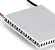
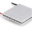
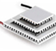
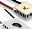
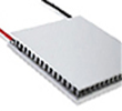
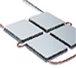

Peltier elements – also known as thermoelectric modules or TECs (Thermoelectric Coolers) – are compact, electrically driven heat pumps. A Peltier element transfers heat from one side of the module to the other, enabling precisely controllable cooling and heating in a minimal footprint. The key advantage: by simply reversing the polarity of the connections, the same Peltier module can both cool and heat – with no moving parts, no refrigerants and no operating noise.
As an experienced distributor, uwe electronic supports you from initial design through to series supply – with a very broad range of Peltier elements for almost any application.
How does a Peltier element work? – The Peltier effect
A Peltier element is based on the Peltier effect, the physical reversal of the Seebeck effect. The Peltier effect describes how heat can be transported through a semiconductor by an electric current. When current flows through the thermoelectric module, a temperature difference builds up between the cold side and the hot side: one side cools down, while the absorbed heat plus the electrical input energy is released on the other side and must be dissipated via a heat sink.
A Peltier element therefore acts like a purely electronically controlled heat pump – fast, precise and continuously adjustable.
Typical applications for Peltier elements
Thermoelectric modules are used wherever temperatures need to be controlled precisely, compactly and with minimal maintenance:
- Medical technology
- Laser technology
- Laboratory and analytical technology
- Gas analysis technology
- Condensation of substances from gas flows
- Automotive technology
- Military and security technology
- Telecommunications and optoelectronics
The advantages of Peltier elements at a glance
- Precise control via the electric current
- Cooling and heating in a single module by reversing polarity
- Vibration-free operation with no moving parts
- Long service life of the thermoelectric effect (> 20 years)
- Small installation dimensions and low weight
- No refrigerants or fluids unlike conventional cooling units
- Silent operation
Peltier elements from uwe electronic – the right module for every application
n the field of Peltier elements, uwe electronic offers a very extensive range that covers a wide variety of applications – from off-the-shelf standard solutions to custom special modules:
- In-stock bestsellers – standard modules available at short notice
- Standard types up to 8 A – for common cooling and heating tasks
- High-power types from 8.5 A – for high heat-pumping capacity
- Cascade types – for particularly large temperature differences up to approx. 120 K
- Peltier elements with a hole – for optical and mechanical special applications
- High-efficiency cycler modules – for frequent temperature changes
- Miniature types – for the tightest installation spaces
- Special types – custom-designed Peltier modules
We also supply matching temperature controllers, heat sinks and thermal interface materials for a perfectly coordinated overall system.
Frequently asked questions about Peltier elements (FAQ)
What is a Peltier element?
A Peltier element is a thermoelectric module (TEC) that uses electrical energy via the Peltier effect to pump heat from one side to the other – providing targeted cooling or heating.
Can a Peltier element both heat and cool?
Yes. By reversing the current direction, the Peltier module switches between cooling and heating mode without any additional components.
What temperature difference can a Peltier element achieve?
Standard modules achieve a maximum temperature difference of around 70 K under vacuum at 27 °C ambient temperature. Multi-stage cascades reach up to approx. 120 K.
How long does a Peltier element last?
With correct design and good heat dissipation on the hot side, the thermoelectric effect remains stable for more than 20 years.
The 30 Golden Rules of Peltier Technology
These practical rules help you optimise the cooling capacity, efficiency and service life of your Peltier element:
- The number of semiconductor pairs and the packing density in the Peltier element determine the module size.
- Each semiconductor pair drops approx. 0.12 V. A high number of pairs therefore results in a higher supply voltage and reduces the required current.
- High currents shorten the service life because they gradually enlarge micro-cracks in the semiconductor material.
- High currents increase internal thermal self-heating (Joule heating) and thus reduce efficiency.
- The ratio of cooling capacity to applied current approaches its maximum exponentially. The last 30 % or so of the maximum cooling capacity therefore requires disproportionately more electrical energy.
- The heat released on the hot side is the sum of the cooling capacity and the applied electrical power.
- The efficiency (COP) of a Peltier element is the ratio of heat-pumping capacity to applied electrical energy.
- You achieve particularly high efficiency when operating below approx. 50 % of the maximum current or voltage value.
- The maximum cooling capacity Qc is specified at a temperature difference of 0 K, maximum current/voltage and 300 K (27 °C) ambient temperature. The real cooling capacity is lower and can be estimated using a performance diagram.
- Standard modules achieve a maximum temperature difference of approx. 70 K under vacuum at 300 K (27 °C).
- High-quality modules exceed 72 K, whereas low-cost modules often reach only just above 60 K.
- Special modules such as multi-stage cascades generate up to 120 K temperature difference – at lower heat-pumping capacity and higher cost.
- Good heat dissipation on the hot side improves cooling capacity, efficiency and the maximum ΔT.
- Heat dissipation to the environment depends on the heat sink: more effective surface area (size and number of fins) reduces thermal resistance.
- Large fans with high airflow reduce the thermal resistance of the heat sink.
- Blowing air frontally onto the heat sink is most effective, as the greatest heat is at the base of the heat sink.
- Liquid heat sinks usually offer better thermal properties but are considerably more cost-intensive.
- A good thermal interface material (thermal pad, film, paste or adhesive) should be used between the Peltier element and the heat sink to keep the contact resistance low.
- A thin layer of thermal paste achieves a very good heat transfer because it adapts optimally to microscopic unevenness and grooves.
- PCMs (Phase Change Materials) have a particularly high fill factor, wet the surface even better than ordinary thermal paste and do not dry out.
- High contact pressure also improves the contact resistance – but always avoid shear forces on the Peltier element during assembly.
- Depending on the Peltier module, the surface pressure should be between 3 and 8 kg/cm2.
- Only small modules up to max. 12 × 12 mm can optionally be metallised and soldered directly onto the heat sink during production.
- The short-term operating temperature should always be 20–30 °C below the melting temperature of the solder (139 °C, 183 °C or 232 °C).
- Continuous operation above 120 °C causes copper to diffuse into the semiconductor material and thus leads to a loss of performance (ageing).
- Only seal Peltier elements when required for condensation protection, as thermal feedback causes approx. 4 % performance loss.
- Silicone sealing is suitable when the module has to adapt flexibly to frequent temperature changes.
- Epoxy sealing does not outgas but is more brittle and unsuitable for temperatures > 80 °C and frequent temperature changes.
- Frequent, large temperature changes create thermal stresses (caused by the different thermal expansion of the materials) and shorten the service life.
- Analogue control and short pulsing stress Peltier elements mechanically far less than a simple two-point control.
Consultation and design support
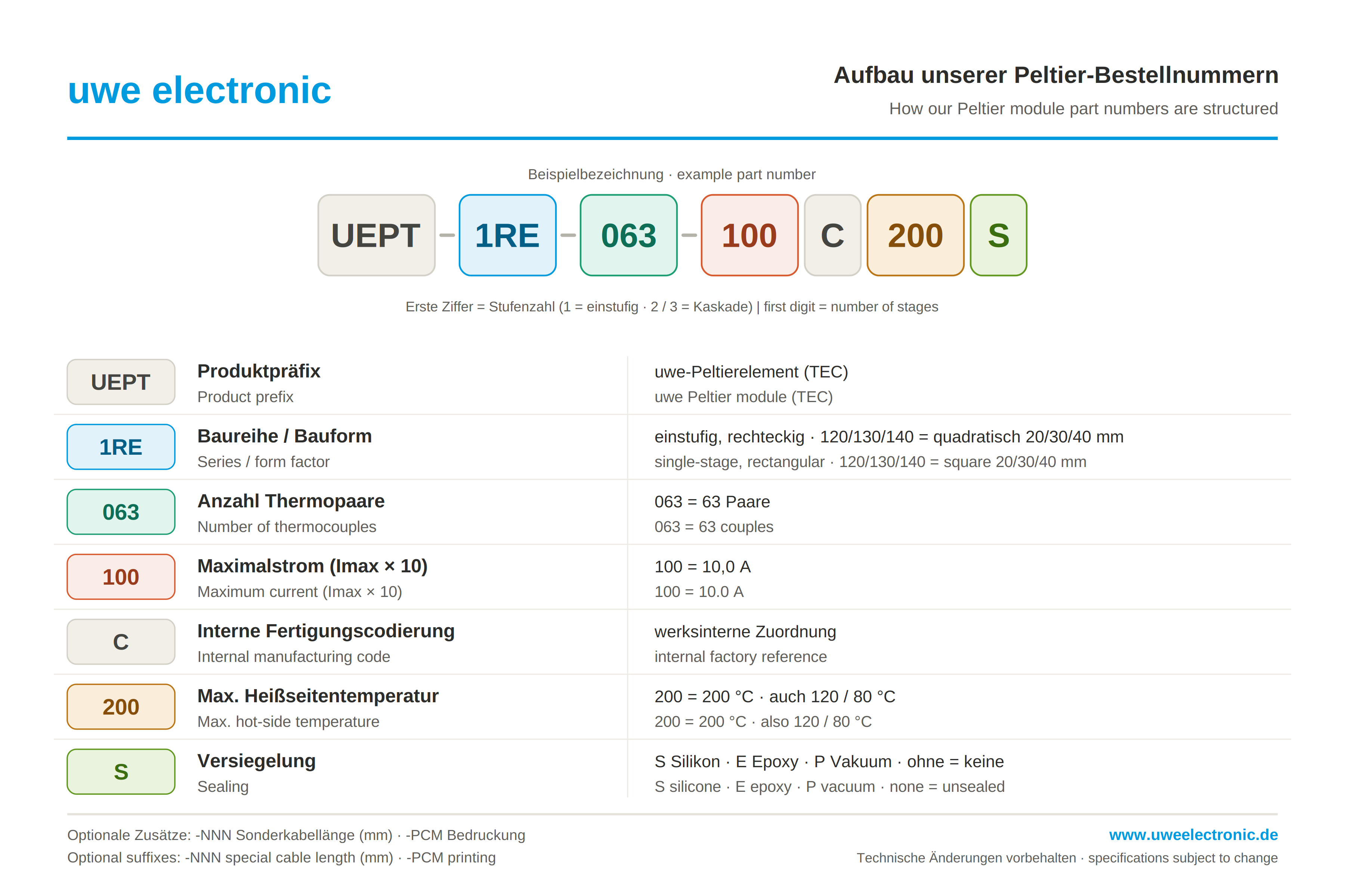
Not sure which Peltier element suits your application? Our team supports you with thermal design and the selection of the optimal thermoelectric module. Get in touch – we love to support you.