
")


Functionality
Thermoelectric Modules - Funktionality
Thermoelectric modules (TEMs) enjoy their primary application of diverse cooling. However, they can be equally used for power generation. Thermoelectric generating modules and coolers are constructed in the same way due to the similarity of the physical processes occurring in them. The major difference between them lies in the assembly techniques employed and the composition of semiconductor material. To give a general outline of how thermoelectric generating modules and coolers are made up, the construction of a most typical cooler is described below.
TEMs utilize the effect that was discovered by Jean Peltier, a French watchmaker. The basic idea behind the Peltier effect is that whenever DC passes through the circuit of heterogeneous conductors, heat is either released or absorbed at the conductors' junctions, which depends on the current polarity. The amount of heat is proportional to the current that passes through conductors.
Material A
Material B
The basic TEM unit is a thermocouple, which consists of a p-type and n-type semiconductor elements, or pellets. Copper commutation tabs are used to interconnect pellets that are traditionally made of Bismuth Telluride-based alloy.
Thus, a typical TEM consists of thermocouples connected electrically in series and sandwiched between two Alumina ceramic plates. The number of thermocouples may vary greatly - from several elements to hundred of units. This allows to construct a TEM of a desirable cooling capacity ranging from fractions of Watts to hundreds of Watts.
When DC moves across TEM, it causes temperature differential between TEM sides. As a result, one TEM face, which is called cold, will be cooled while its opposite face, which is called hot, simultaneously is heated. If the heat generated on the TEM hot side is effectively dissipated into heat sinks and further into the surrounding environment, then the temperature on the TEM cold side will be much lower than that of the ambient by dozens of degrees. The TEM's cooling capacity is proportional to the current passing through it. TEM's cold side will consequently be heated and its hot side will be cooled once the TEM's polarity has been reversed.
Choice of peltier modules
How to choose peltier modules
Item key:
UEPT-140-127-085C200S
1: Type 1 stage peltier module
40: Dimension 40x40mm
127: Amount of p/n-thermo couples
085: Maximum current 8,5 Ampere
C: Factory key
200: Maximum operating temperature
S: Sealing with silicone
Given data valid for Tu=300K (27°C):
Qc-max: Maximum cooling power @ deltaT=0°C and Umax / Imax
deltaT-max: Maximum temperature difference @ Umax / Imax and Qc=0 Watt
Performance diagram UEPT-140-127-085C200S
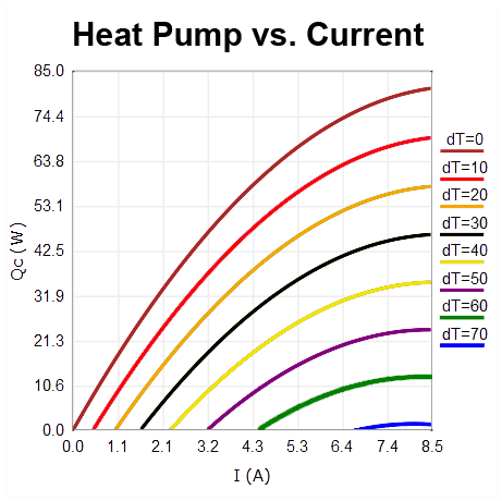
Diagram does show that cooling power Qc is decreasing with rising deltaT. Moreover the relationship Qc / current in the first 50% of Imax is almost linear while in the second half of Imax further outcome is decreasing exponentially. Math function is also called as exponential alignment to the maximum value.
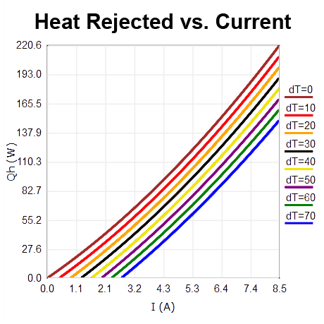
The sum of thermal power on Peltier’s hotside is the sum of transported thermal volume and electrical working power: Qh = Qc + Qel.
For the right choice of peltier module the heatsink´s ability of thermal heat rejection to ambient air need to be considered. The calculation of deltaT of both sides of the peltier module is possible with the heat sink´s value of thermal resistance.
Too high current can lead to excessive demand of the heatsink. Most efficient operation of the peltier module is in the first half of maximum current.
A high deltaT is reached with low current / voltage. By operating with high current / voltage one will reach a high volume of heat being pumped.
Performance graph Peltier modules
Performance graph Peltier modules
Following graphs show cooling power at various temperature differences:
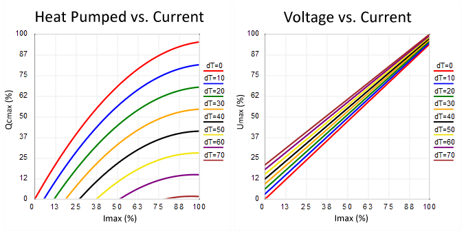
The diagram heat pumped vs. current shows that with rising deltaT the current value decreases. The cooling power Qc can be determined in the diagram through the current value. The maximum value of the cooling power can also be taken from the tables of the Peltier modules.
The diagram “voltage versus current” shows the linear relationship of both values. The particular maximum values can be taken from the value table of the peltier module. Very often peltier modules are actuated with 50-75% of Umax or Imax.
Mounting
Mounting
Peltier modules are usually get clamped between heatsink and according body that need to be chilled. To decrease thermal contact resistance interface materials like thermal pastes or foils are used. Some thermal pastes are available with silicone ingredients. This material can dry out and is often not appropriate for optical applications.
A high contact pressure also improves the thermal property. In dependence of the individual Peltier module a contact pressure of 30-80 N/cm ² is recommended. During assembly it is important that force is evenly spread. Otherwise shearing forces could crack the internal solid-state easily.
During assembly it is necessary to pay attention to the proper installation of the wires of the Peltier module to get the cold side and hot side on the correct side of the module. At given polarity hot side is where the wires are soldered.
Interface materials
Comparison of the thermal resistance at different interface materials
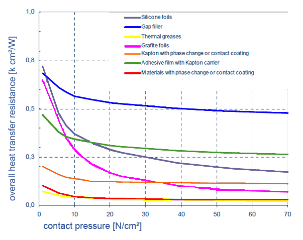
The diagrams shows a clear reduction of thermal resistance in dependence of the surface pressure for all relevant materials.
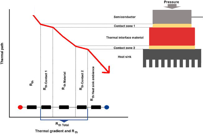
During assembly of Peltier modules beside of thermic contact resistance also the value for heat transfer resistance between both surfaces (Peltier module & Heat sink) is important. The whole thermal resistance is defined:
Rth = Rth Interface material + Rth contact area 1 + Rth contact area 2
A high contact pressure, a low rough depth of the surfaces as well as an excellent matching of interface material to the surface structure with low viscosity improve the thermal resistance. Phase change material has got the characteristic at its phase change temperature to squeeze out air of the surface compound.
Possible interface materials:
1. Thermally conducting Phase Change Material (PCM)
Phase change material moisten the surface above its phase change temperature and squeezes out air inclusions. By the fact that the phase change material extends at rising temperature in volume the moistening of the contact surfaces is improved. Moreover, convex and concave unevenness of the surfaces and other tolerances can be compensated very well.

Due to the thixotropic flow characteristic a leakage of material is not possible. The thickness of PCM is spread equally on the surface and is an ideal substitute for thermal paste.
Peltier modules can be prepared with PCM on its surface that is dry under normal temperature conditions. Due to heating up the module to the PCM relevant temperature during the assembling process the module will be connected to any application it will be built in.
Characteristics and advantages:
- Very low thermal resistance up to 0.2 K-cm2/W
- Silicone free
- No dehydration, migration or leaking
- Steady thickness in process
- Preapplication with PCM possible
2. High thermic conductable Gap-Filler
High thermic conductable Gap-filler reach extreme thermal conductivities from 10 W/mK up to 50 W/mK. An excellent thermal surface contact is reached by its high softness and therefore mechanical tolerances can be compensated very well.
Characteristics and advantages:
- Thermal conductivities of 10 W/mK up to 50 W/mK
- Thermal resistance less than 0.4 K-cm²/W
- Thickness from 0.2 to 2.0 mm
- Very good surface adaptation and thermal contact due to high viscosity
- Very good compensation of mechanical tolerance
3. Graphite foils
Graphite foils consist of more than 98% pure graphite. By its internal structure it shows anisotrope thermal conductivities in foil level. Thermal power in hot spots can be spread and precisely directed to a larger area. By its softness it adapts very well to the surfaces so that the thermal transitional resistance is minimised.
Characteristics and advantages:
- Thermal conductivities up to 200 W/mK in the level and 5W/mK in z-direction
- Very good warm derivation of hot spots
- Thermal opposition less than 0.5 K-cm²/W
- Low thermal transitional resistance
- Very low weight
- Silicone free
- High temperature withstand about 300 °C
- No dehydration, migration or leaking
5. Thermic adhesive paste
Thermic adhesive bonding systems are available as silicone and acrylate based two component glues. These are curing normally at ambient temperature. This material represent a good alternative to other PCM´s due to its well bonding characteristics and its high conductivities up to 2.8 W/mK.
The adhesive solutions are appropriate for easy, effective and reasonable thermal binding of heat sinks to Peltier module. All above shown adhesive solutions are used in case screwing or clamping connections are not possible.
Characteristics and advantages:
- Good thermal resistance by minimum thermal contact resistance
- Reliable long-term adhesive strength on uneven and difficultly treated surfaces
- High balance of mechanical tolerance
- Alternative to mechanical connections like screws or clips
Protection against humidity and corrosion
Protection against humidity and corrosion
In the continuous operation Peltier modules can reach dew point of air easily. This humidity can lead to corrosion of the copper bridges inside of the module or follows to a short circuit. Condensed water is also a warm-leading connection between both ceramic plates of the module. Therefore is protection against moisture a common requirement.
There are optionally sealed versions with silicone or epoxy available, to protect the Peltier modules against humidity. In most cases silicone is used, because material can adapt itself better to frequent temperature changes.
For optical devices very often the use of silicone as material is banned. Reason is the possibility of outgassing. In this case epoxy as material would be the better choice, as long as the maximum operating temperature does not exceed 80°C. Water receptiveness of the epoxy sealing is also a little lower in comparison to silicone.
Silicone and epoxy sealing decreases the efficiency of a Peltier module through to thermal heat back-coupling of about 3-4%. At the end of the item key indicates "S" a silicone and "E" an epoxy sealing.
Stability against thermal and mechanical influence:
Thermoelectric modules are often used in systems where vibrations or shocks are possible. To evidence the applicability of peltier modules for these purposes, different test procedures are applied. For the high quality modules the following high-class test is done to verify temperature resistance as well as the resistance of shock and vibration:
High Temperature Operations and Storage: >30.000 hours @ 150°C
Low Temperature Operations and Storage: >1.000 hours @ -40°C
Thermal shock:
(I) 100°C (15 sec)/100°C (15 sec), 10 cycles
(II) 150°C (5 min)/-65°C (5 min)/ 150°C, 10 cycles
(III) MIL-STD-202, Method 107
Mechanical Shock:
(I) 100G, 200G 2 6msec; 500G, 1000G @1 sec 3-axis, three shocks each axis
(II) MIL-STD-202, Method 213, Test Condition I
Vibration:
(I) 10/55/10 Hz, 1 minute cycle, 9.1G, 3-axis, 2-hours each axis
(II) MIL-STD-202, Method 204A, Test Condition B, 15G Peak
Technische Änderungen und Irrtürmer vorbehalten. | Specifications subject to change without notice!